How to use Dual Force Plates with Swing Catalyst
Swing Catalyst Dual Force Plates
Setup, calibration, and troubleshooting guide for the Swing Catalyst Dual Force Plate system, which measures Ground Reaction Forces and Center of Pressure (CoP).
Quick-start overview
- Connect both plates via USB.
- Launch Swing Catalyst, plates are detected automatically.
- Open Settings → Hardware → Sensor Plate → Configure.
- Tare (zero) the plates with nothing on them.
- Run component detection (identify back plate).
- Verify with Live Preview, then start recording.
Related articles
1. Requirements
- Swing Catalyst 25.3.4 (or newer) installed and up to date.
- A pair of Swing Catalyst Dual Force Plates.
- One available USB port per plate.
Info
No manual driver installation is required. Swing Catalyst detects the plates automatically when connected.
2. Setup
Follow these steps in order. Each step builds on the previous one.
2.1 Connect the plates
Each plate needs a single USB cable. Ideally, route both cables together underneath the back plate to keep things tidy.
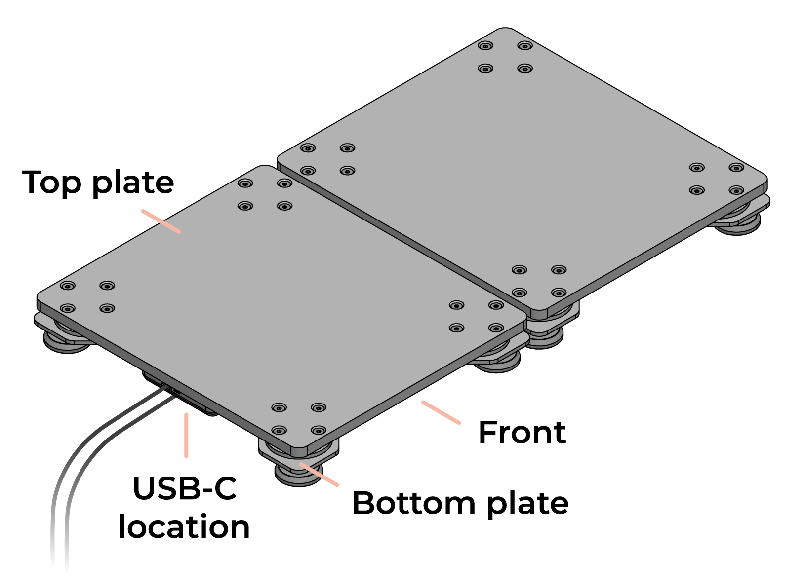
Cable routing — both USB cables exit opposite the hitting direction.
- Orient the plates so the USB cable exits opposite the hitting direction.
- Connect one USB cable from each plate to the computer (or a USB hub).
- Launch Swing Catalyst.
- The software will automatically detect the connected plate(s).
Navigate to the settings menu (gear icon)

Bottom left hand corner of Swing Catalyst.
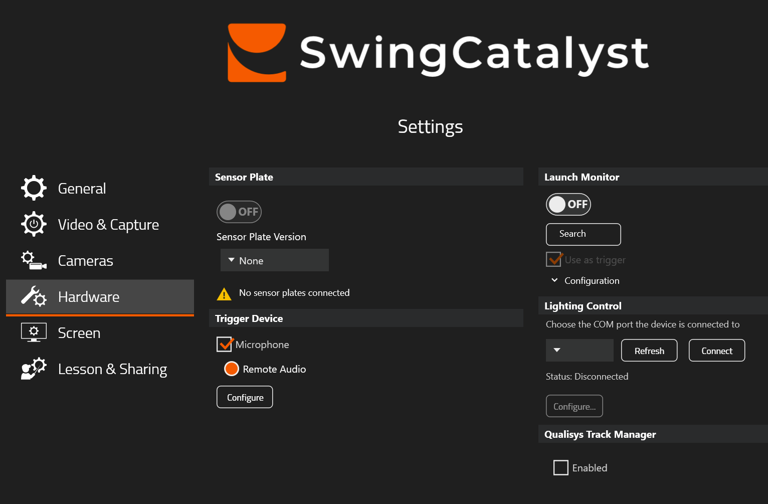
Hardware settings.
Plates detected successfully (no zeroing has been done yet).
Tip
A powered USB hub is recommended if your computer has limited USB ports. Please see the bottom of this article for USB extender and hub recommendations.
If the plates are not detected, try disconnecting and reconnecting the USB cable(s) and restarting the software. See Troubleshooting for more help.
2.2 Tare (zero) the plates
Taring resets the sensors to zero, removing any offset caused by the plate surface weight or environmental factors. Do this before every recording session.
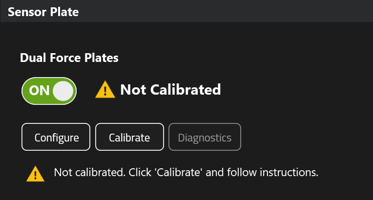
- Open Settings → Hardware → Sensor Plate and clickConfigure.
- Make sure no one is standing on the plates and they are free from objects or surrounding turf.
- Click Tare in the Sensor Plate Configuration dialog.
- Wait for the taring process to complete.
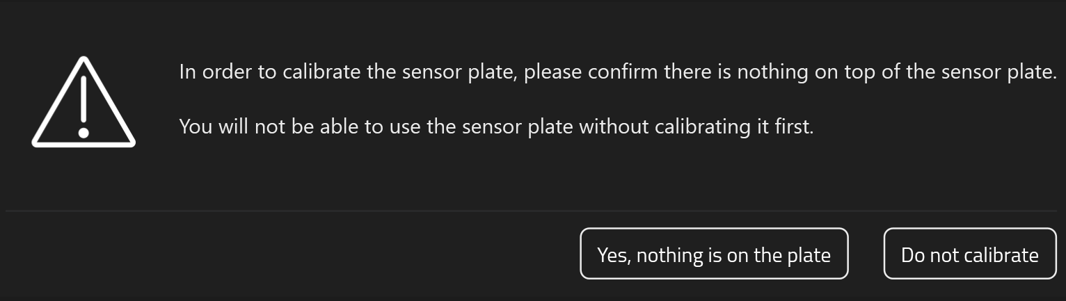
Confirm nothing is on the plates when performing the zeroing routine.
Warning
If anything is on or touching the plates during taring, all subsequent force readings will be offset and unreliable.
2.3 Detect front & back plates
The software needs to know which physical plate is front and which is back. This is done automatically:
- In the Sensor Plate Configuration dialog, click Detect.
- When prompted, step onto the back plate (trail foot).
- The software will assign front and back roles accordingly.
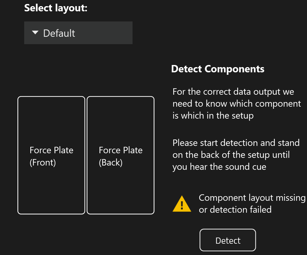
Click Detect to start the component detection process.
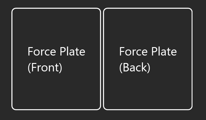
Front and back force plate positions.
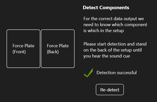
Successful detection.
2.4 Layout & plate positioning
Layout selection
In most cases the default layout is correct. The available options are:
- Default — plates oriented normally per installation recommendations.
- Rotated — both plates rotated 90° to allow a wider stance.
Info
The Rotated option is mainly useful for the 60 × 35 cm model. Other models are almost square so you can simply increase the spacing between plates instead, see below.
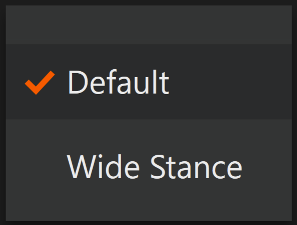
Layout selection, the default is correct in most cases.
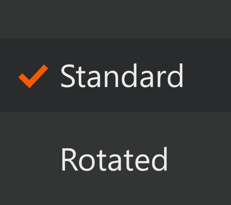
Available layout options.
Plate spacing
Below the layout options you can choose the gap between the two plates:
- Narrow — little to no gap (default).
- Wide — 22 cm gap for a wider stance.
- Custom — define your own spacing.
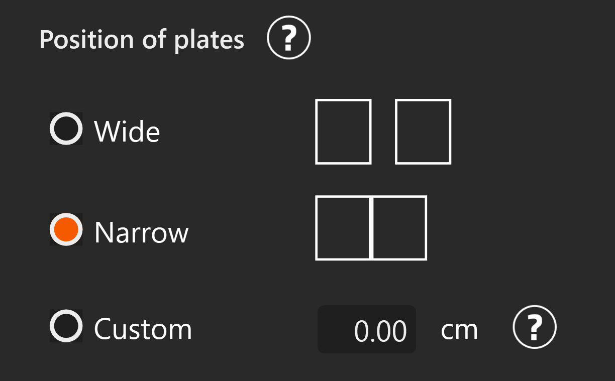
Plate position options.
Warning
Incorrect spacing values will affect force and CoP calculations. Measure the actual gap if using a custom value.
2.5 Verify with Live Preview
Click Start Preview in the configuration dialog to see real-time CoP data. This confirms the plates are working correctly before you start a capture session.
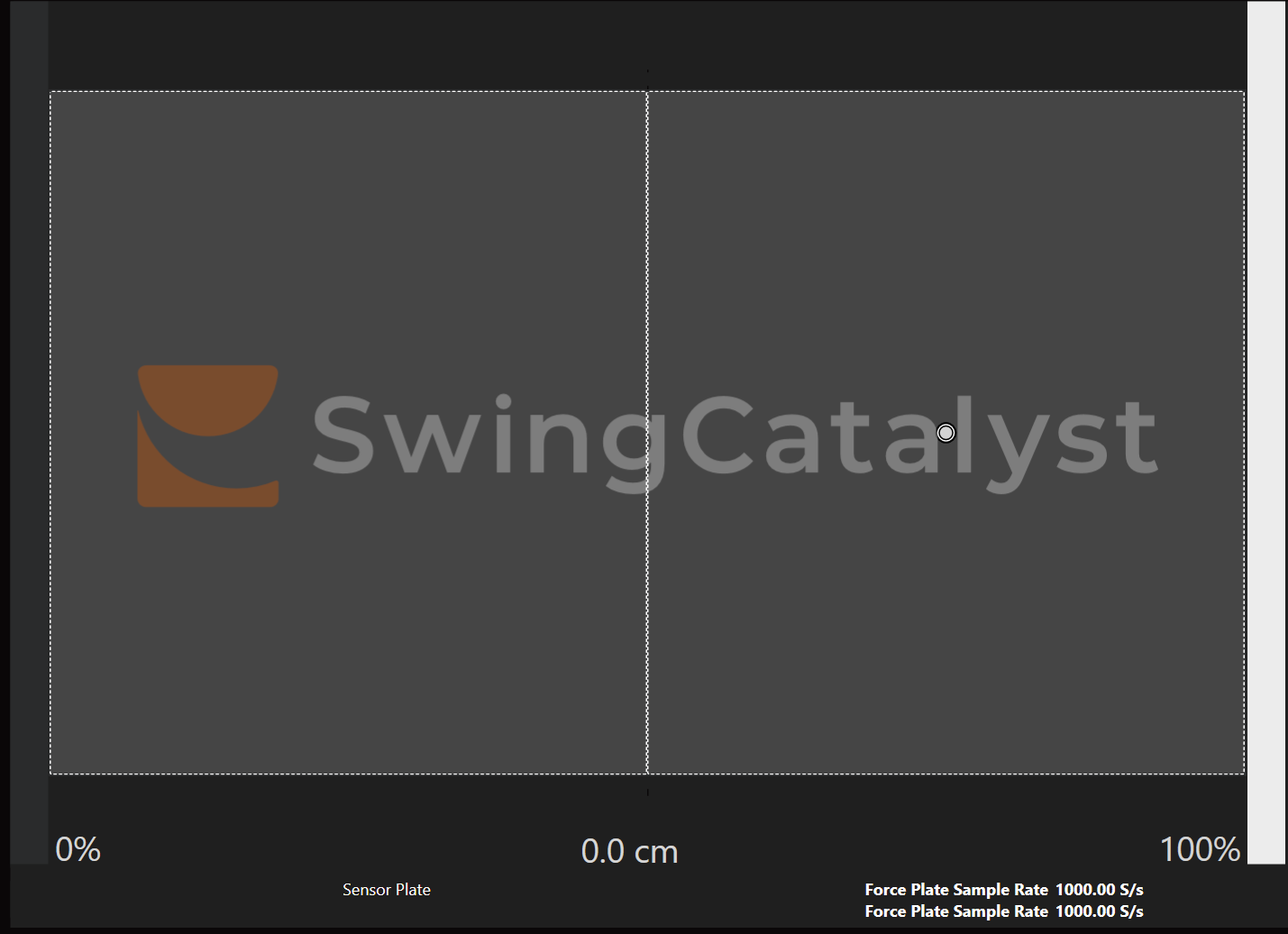
Live preview showing real-time Center of Pressure. In this example the subject is standing in the center of the right plate.
2.6 Calibration test
After taring, run through these checks to confirm everything is accurate:
- With nothing on the plates, click Tare, then clickStart Preview.
- Step onto a plate and shift your weight around. The CoP indicator should move in the expected direction (lean forward → CoP moves forward).
- For dual plates, stand on each plate individually and verify CoP appears on the correct side.
3. Recording
Once setup and taring are complete, the plates are ready. Force data is captured automatically alongside video when you start a recording in Swing Catalyst.
The plates record the following data at up to 1000 Hz:
- Ground Reaction Forces (Fx, Fy, Fz) — horizontal and vertical forces in three axes.
- Center of Pressure (CoP) — the point on the plate surface where force is applied.
This data appears in the analysis view as CoP traces, force graphs, and force vectors — useful for evaluating weight shift, balance, and ground interaction.
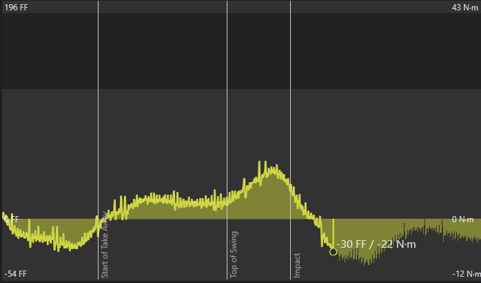
Good data vs. bad data
Good data shows smooth force curves with very little noise. At rest, force values should be near zero.
If CoP is offset or any of the force channels have a load at rest, try to re-zero the plates.
Below are some example screenshots meant to be used as a reference.

Good data — smooth curves.
Bad data — excessive noise and erratic values. See Troubleshooting .
4. Troubleshooting
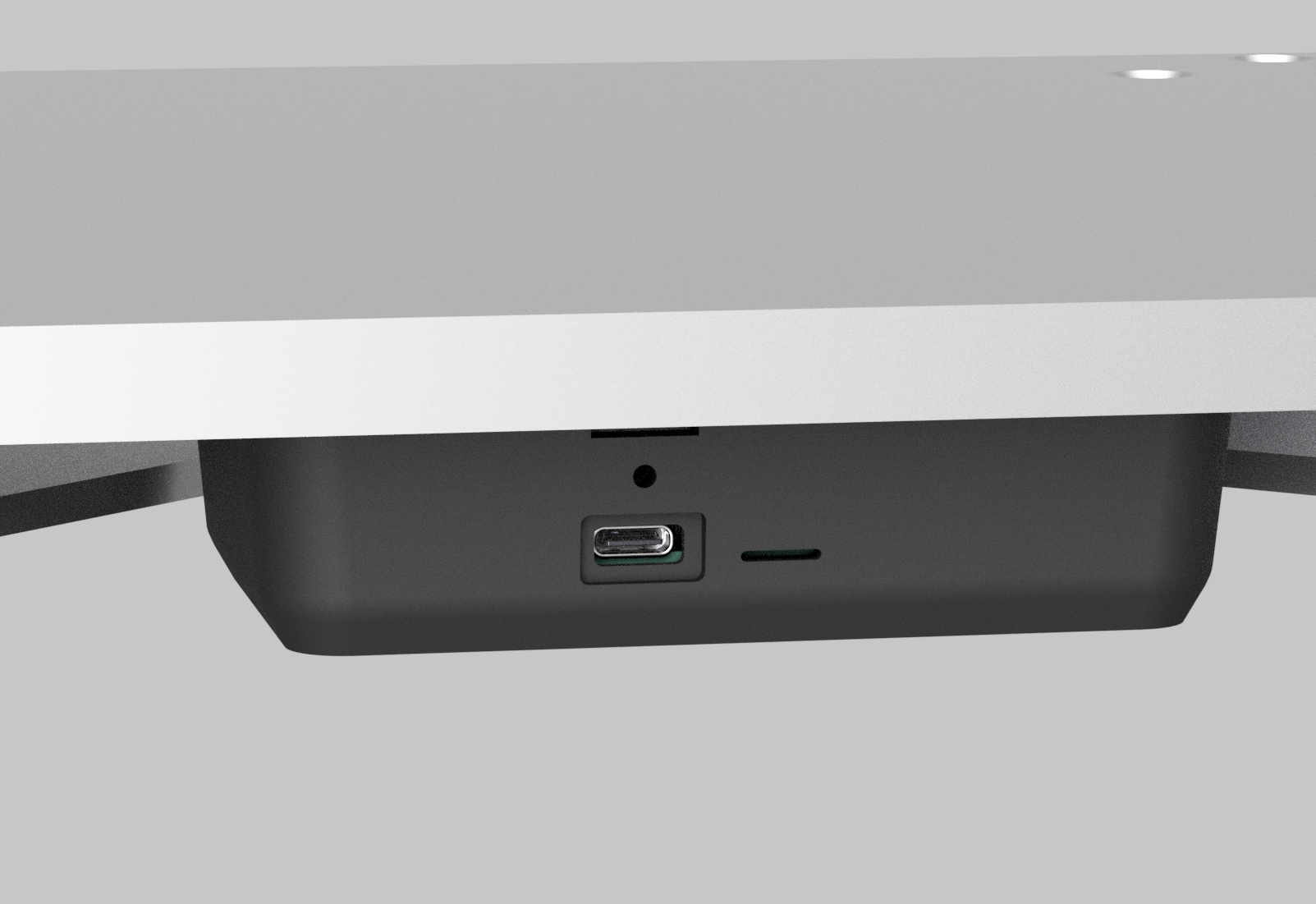
USB port and LED indicator location.
LED indicator reference
A small LED on each plate shows its current status. Use this to quickly check whether the plate is powered and streaming.
| Color | State | Meaning |
|---|---|---|
| Green | Solid | Powered on |
| Blue | Blinking | Data is streaming |
| Red | Solid / blinking | Error: see Troubleshooting |
Plates not detected
- Disconnect and reconnect the USB cable(s).
- Try a different USB port or hub. Avoid front-panel USB ports on desktop computers.
- Disconnect and reconnect any USB extenders.
- Restart Swing Catalyst.
- Ensure Swing Catalyst is version 25.3.4 or newer.
Only one plate detected in a dual setup
- Check that both USB cables are firmly connected.
- Open the Sensor Plate Configuration dialog — it should show two serial numbers for a dual setup.
- Try swapping the USB cables or ports to isolate the issue.
- Restart the software after reconnecting.
Taring fails
- Ensure nothing is on or pressing against the plates.
- Verify the plates are on a flat, level surface.
- Disconnect and reconnect the plates, then try again.
CoP data appears incorrect or jumps unexpectedly
- Re-tare the plates with nothing on them.
- Ensure the plates are level and not touching surrounding turf, mats, or other equipment.
- Confirm all feet of the plate are in solid contact with the floor. If the plate rocks on corners, adjust the leveling feet.
Noisy or non-zero force readings at rest
- Re-tare the plates.
- Check that nothing is touching the plates (turf edges, cables, equipment).
- Electrical noise from power supplies or poor grounding can cause issues. Connect the computer and plates to the same power strip, or try a different outlet.
CoP is 180° wrong (moves opposite to your weight shift)

Example: CoP dot moves opposite to actual weight shift.
The force data rotation needs correcting. See How to rotate force data below.
Wrong plate detected during component detection
The plate assignment is likely swapped. Click Detect again and step on the correct plate when prompted.
5. Reference
Rotating force data
If the CoP indicator moves opposite to your actual movement, you can correct the rotation in software instead of physically turning the plate.
- Go to Settings → Hardware → Sensor Plate and clickConfigure.
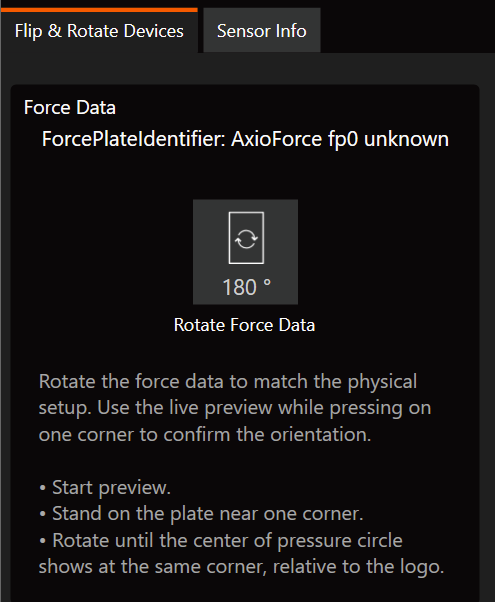
- Select the Flip & Rotate Devices tab.
- Find the force plate entry and click Rotate Force Data to rotate 180°.
- For dual setups, check and correct each plate individually.

Rotate Force Data controls in the Sensor Plate Configuration dialog.
After rotating, use the Live Preview to verify the CoP now moves in the correct direction.
Finding your serial number
You may need the serial number when contacting support or for repair purposes.
- Go to Settings → Hardware → Sensor Plate and clickConfigure.
- Select the Sensor Info tab.
- The serial number for each connected plate is displayed here.
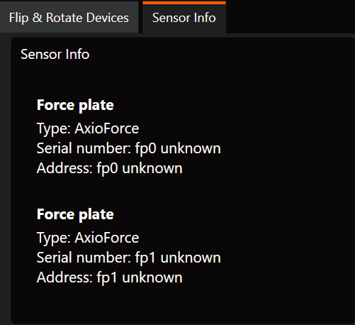
Serial numbers in the Sensor Info tab.
Recommended USB components (extenders & cables)
If you need to extend the USB cable run, the following product has been tested and confirmed to work reliably: