How to use Force Vectors
Introduction
This article aims to demonstrate the new force vectors feature in Swing Catalyst 10.0. Force Vectors are available to those with Motion Plates (dual or single) or force plates (dual or single).
Force vectors are shown in real time over the video image when streaming video or during capture, and are also visible during playback.
By representing ground reaction forces as vectors (arrows) that are rendered on top of the video image, we hope to make movement easier to understand.
Supported hardware:
Dual Motion Plate
Motion Plate 6, and 5.
Dual Force Plates.
Single Force Plates
Note: It’s possible to view recordings with force vectors in any Swing Catalyst software without any additional hardware.
Force Vectors - Introduction
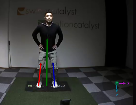
Force vectors show ground reaction forces on top of the video image, both live in real time in capture mode, or during playback. In the bottom right corner of the each video image (camera angle) there is a graphic showing the coordinates of the vectors in 3D space.
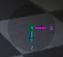
The coordinate representation differs depending on the camera angle.
The coordinate graphic that the Z axis is vertical, and Y and X are horizontal, using the same colors as our force graphs.
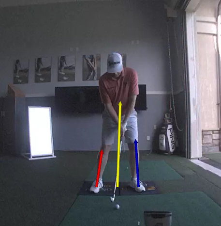
The magnitude of the force vectors are accurate respective to the real world, meaning that (if calibrated correctly), a vector 1 meters in height equals 1000 newtons.
Force Vectors - Calibration
A calibration is necessary to use force vectors, this is to identify *where *the plate is located in the video image. Calibration needs to be done only once for each camera angle. If the camera(s) or plate(s) change physical location a new calibration is required.
Please note that for old recordings it’s necessary to calibrate each recording, it’s not retroactive as we have no way of knowing where the plate is in the video image. It’s important to do the calibration in capture mode so that it’s stored automatically with each new recording.
In 10.2 and newer the force vector calibration can be found under “Data Visuals”
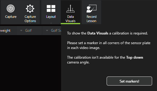
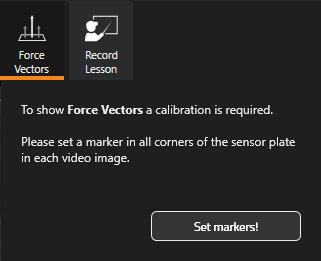
Click “Set markers!” to begin the calibration process.
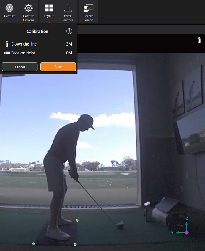
Click on each corner of the plate to set the markers. For dual plates click two of the outer corners of both plates.
Repeat the process for the other camera angles.
If you make a mistake just ignore it and complete the process for the angle you are working with and begin again by clicking a corner.
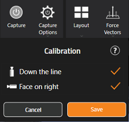
Click “Save” when done.
Force Vectors - Options
From this drop down menu you can access all of the options related to force vectors.
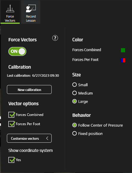
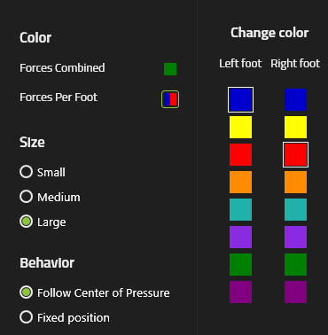
Click the color “icon” to change the color.
Illustration of selecting between different colors:
Troubleshooting
The force vectors originate from the same spot even though the calibration is correct and I have a dual force / motion plate setup.
If the camera angle is incorrect this might be the cause.
Imagine if you’re viewing the below image in the direction of the X arrow (see the purple arrow in the bottom right of the image).
All of the force vectors are rendered at the same depth. If viewed from the side it would appear to be originating from one spot.
Note it’s not possible to change the camera angle for recordings that are already created. It’s important to make sure this is correct before recording.