Dual Force Plate installation guide
Overview
This article covers the Swing Catalyst Dual Force Plates (2026 variant).
Related Articles
Handling
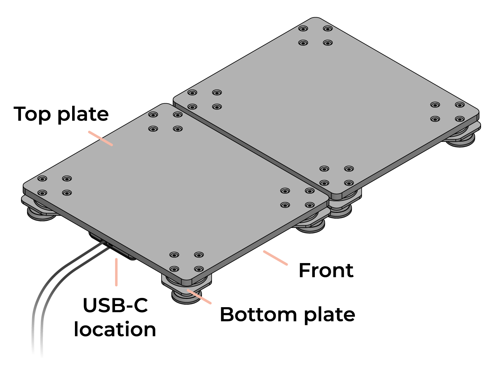
Always lift the force plate by the top plate only. If the plate is upside down, do not use the feet or bottom plate to lift it.
Warning: Do not adjust the feet. Although they appear adjustable, they are factory-calibrated. Tightening or loosening the nuts may damage the sensors and void your warranty.
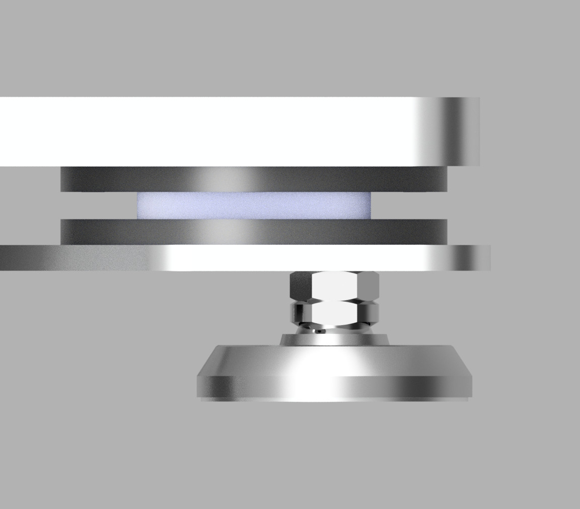
The feet are not adjustable
Placement
Surface Requirements
Place the force plates on a flat, level, and rigid surface. Level concrete or similar rigid flooring is ideal.
After placing the plates, verify that they do not wobble or shift. All four feet must make firm contact with the floor.
Note: Soft or uneven surfaces, such as turf, dirt, wood, or carpet may cause inaccurate readings and reduce data quality.
Spacing
Leave at least a 3 mm gap around and between the force plates. The plates must not touch each other or any surrounding objects, as contact will interfere with readings.
Storage
Store the force plates upright, resting on all four feet. Plates may be stacked for storage. Do not store them upside down (top plate facing down) or place heavy objects on top, as this may void your warranty.
Usage & Environment
We recommend using the plates indoors in a controlled environment. While the force plates are robust and can tolerate some humidity, prolonged exposure to high moisture and or water may cause corrosion and eventually cause damage to the electronics.
Installation
The dual force plates are designed for portable or semi-portable use. We do not currently recommend installing the plates in an enclosure or pit.
Warranty
This Limited Warranty covers defects in materials and workmanship for a period of two (2) years from the date of purchase. In addition, you may return the product for any reason within90 days of purchase for a full refund, less shipping and handling fees.
Technical Specifications
All measurements in the drawings below are in millimeters.
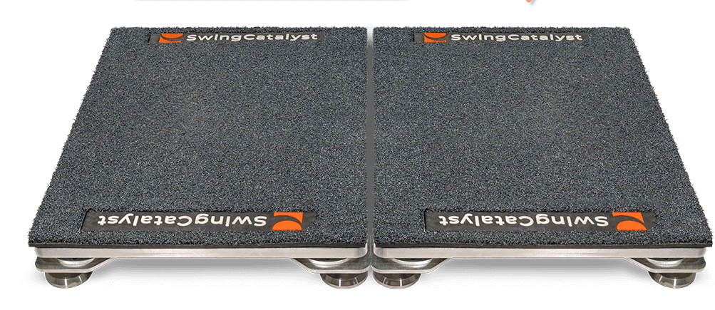
The included logo mat / turf adds approximately 15–20 mm to the overall height.
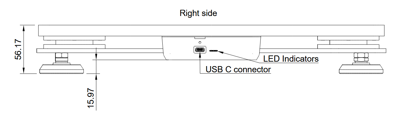
Right side view: USB connector and LED status indicator (mm)
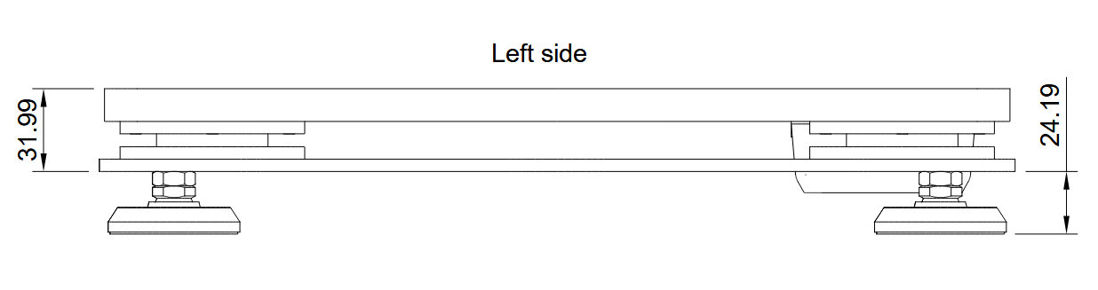
Left side view: hitting direction (mm)
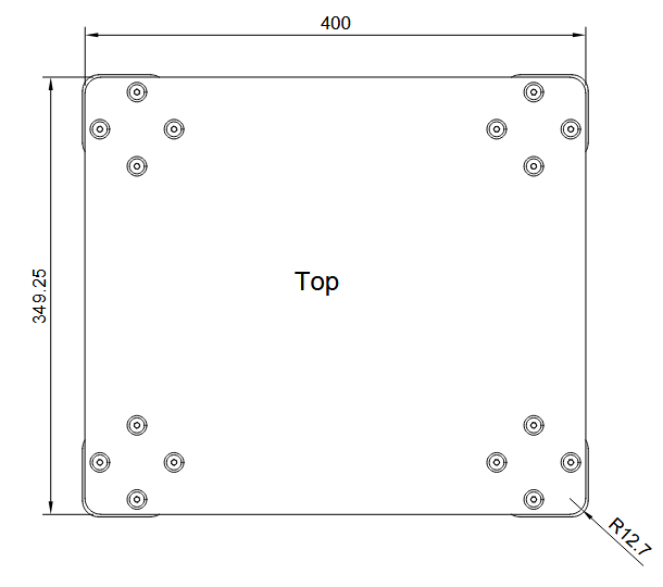
Top view (mm)
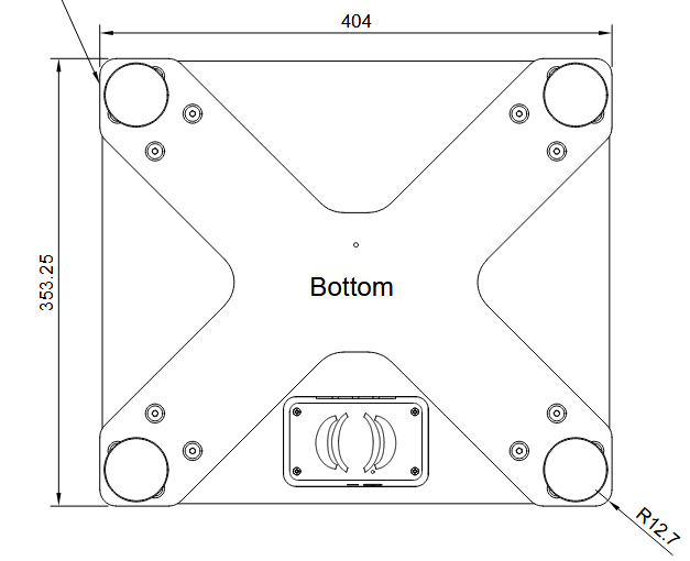
Bottom view: electronics housing & underside of force plate (mm)
Dimensions & Capacity
| Configuration | Size (mm) | Weight (kg) | Max Range | Sampling Frequency |
|---|---|---|---|---|
| Single plate | 401.3 × 350.5 × 57.2 | 7.26 | 7,000 N | 1,000 Hz |
| Both plates | 802.6 × 350.5 | 14.51 | 14,000 N | 1,000 Hz |
Accuracy
| Axis | Absolute Error* | Relative Error (% FS)** |
|---|---|---|
| Fx | 0.71 N | 0.07% |
| Fy | 0.66 N | 0.07% |
| Fz | 3.86 N | 0.08% |
| Mx | 0.71 N·m | 0.07% |
| My | 0.63 N·m | 0.06% |
| Mz | 0.10 N·m | 0.02% |
* Mean Absolute Error across full measurement range ** Mean Error normalized to Max Range (Percent Full Scale)
Last updated: 2026-03-20 | View on official support site